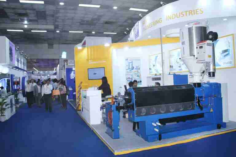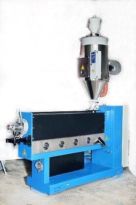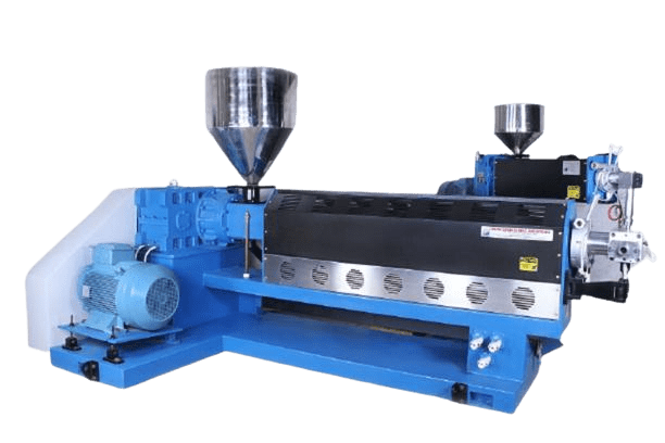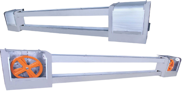

A single screw extruder is a very important machine in plastic manufacturing factories. The job of this machine is to heat the raw plastic, mix it well, and then push it forward to form a new shape. With its help, pipes, sheets, films, and many other types of plastic products are easily made.
Saini Engineering is a leading extruder manufacturer that offers strong and durable single screw extruder machines. These machines are designed to give good performance for a long time and consume less electricity.
In this blog, we will explain to you about the single screw extruder diagram, its parts, working principle, and design calculation.
What is a Single Screw Extruder Machine?
Single Screw Extruder Machine is a machine that is most commonly used in the plastic manufacturing industry. This machine has a long screw that rotates inside a barrel. When raw plastic is put into it, the screw pushes it forward, heats it with a heater in the middle, and mixes it well. Finally, the plastic melts and comes out of the die and is prepared in the form of a pipe, sheet, or other shape.
Single Screw Extruder Diagram Overview
A typical single screw extruder diagram consists of several important components working together to ensure smooth material processing.
Main Components in an Extruder Diagram
1. Hopper
The hopper stores and feeds raw material into the extrusion system. Plastic pellets, powders, or granules are introduced through this section.
2. Feed Throat
This section connects the hopper to the barrel and allows material to enter the screw channel.
3. Barrel
The barrel houses the rotating screw and contains heating zones that gradually increase material temperature.
4. Screw
The screw is the most important component in the machine. The screw diagram generally includes three functional zones:
- Feed Zone
- Compression Zone
- Metering Zone
Each section performs specific functions during the extrusion process.
5. Heating Bands
Electric heaters mounted around the barrel generate controlled heat for melting materials.
6. Motor and Gearbox
The motor provides rotational power while the gearbox controls screw speed and torque.
7. Screen Pack
This component filters contaminants and ensures uniform melt quality.
8. Die Head
The die gives the final shape to the molten material before cooling.
9. Cooling System
The product is cooled using air, water, or specialized cooling equipment.
10. Control Panel
Modern extruders include advanced control systems for monitoring temperature, pressure, and production parameters.
Understanding the Screw Diagram
The screw diagram is divided into three major sections that determine extrusion efficiency.
Feed Zone
The feed zone receives raw material from the hopper and transports it forward. Deep screw channels allow easy movement of solid material.
Functions:
- Material conveying
- Initial heating
- Bulk density control
Compression Zone
The compression zone gradually reduces channel depth, compressing the material and generating heat through friction.
Functions:
- Material compression
- Air removal
- Initial melting
Metering Zone
The metering zone ensures a uniform melt before the material reaches the die.
Functions:
- Melt homogenization
- Pressure generation
- Consistent product quality
Main Parts
- Hopper: From where the plastic is put into the machine.
- Barrel: The part of the machine in which the screw rotates.
- Screw: Pushes and mixes the plastic forward.
- Heater Bands: Heat the plastic.
- Die Head: Gives the final shape.
- Motor & Gearbox: Drives the screw.
Single Screw Extruder Working Principle
The Single Screw Extruder is the heart of modern plastic processing – turning raw plastic into pipes, sheets, films, and profiles with precision and efficiency. Single Screw Extruder is a machine used to process plastic by melting, mixing, and shaping it. It works using a single rotating screw inside a heated barrel, which pushes the material forward.
- Feeding: Raw plastic materials, usually in granules or powder form, are fed into the hopper. The screw starts moving them forward inside the barrel.
- Melting: As the plastic moves along the barrel, heat from heater bands and friction from the screw gradually melt the material. The plastic softens and becomes uniform.
- Mixing and Compressing: The screw continues to push the molten plastic, mixing it thoroughly and building pressure to ensure smooth flow.
- Extrusion/Shaping: Finally, the melted plastic is forced through a die at the end of the barrel. The die shapes the plastic into pipes, sheets, films, or other profiles.
Extruder Machine Parts and Their Functions
| Extruder Machine Parts | Function |
|---|---|
| Hopper | Stores raw material |
| Feed Throat | Transfers material into barrel |
| Barrel | Houses screw and heating zones |
| Screw | Conveys and melts material |
| Heater Bands | Provide process heat |
| Gearbox | Controls speed and torque |
| Motor | Drives screw rotation |
| Screen Pack | Filters contaminants |
| Die Head | Shapes product |
| Cooling Unit | Cools finished product |
| Control System | Monitors operations |
Understanding these extruder machine parts is essential for maintenance and process optimization.
Extruder Screw Design Calculation
One of the most important engineering aspects of extrusion is extruder screw design calculation. Proper screw design directly affects output, melting efficiency, energy consumption, and product quality.
Several parameters are considered during screw design:
Screw Diameter (D)
The screw diameter determines processing capacity.
Typical Range:
- 20 mm to 250 mm
Length-to-Diameter Ratio (L/D Ratio)
The L/D ratio influences melting and mixing performance.
Common Ratios:
- 20:1
- 24:1
- 30:1
- 36:1
Compression Ratio
The compression ratio is calculated using:
Compression Ratio = Feed Channel Depth ÷ Metering Channel Depth
Typical values:
- 2:1
- 3:1
- 4:1
Screw Speed
Measured in RPM and selected according to material characteristics and output requirements.
Throughput Capacity
Calculated based on:
- Screw diameter
- Screw speed
- Material density
- Channel geometry
Proper extruder screw design calculation helps maximize productivity while maintaining product consistency.
Screw Design for Extrusion
The effectiveness of extrusion largely depends on proper screw design for extrusion.
Key Design Factors
Flight Depth
Controls material conveying and compression.
Pitch
Determines material movement speed.
Compression Ratio
Affects melting performance.
Mixing Section
Improves material uniformity.
Venting Design
Removes trapped moisture and gases.
Advanced screw designs can significantly improve production efficiency and reduce energy consumption.
Applications of Single Screw Extruders
Single screw extrusion technology is used in numerous industries.
Plastic Industry
- Pipes
- Tubes
- Sheets
- Films
- Profiles
Packaging Industry
- Flexible packaging films
- Lamination products
Cable Industry
- Wire insulation
- Cable sheathing
Recycling Industry
- Plastic pelletizing
- Waste plastic processing
Food Industry
- Snacks
- Pasta
- Pet food production
Medical Industry
- Tubing
- Medical-grade polymer products
Difference Between Single Screw and Twin Screw Extruder
Many manufacturers compare the difference between single screw and twin screw extruder before selecting equipment.
| Feature | Single Screw Extruder | Twin Screw Extruder |
| Number of Screws | One | Two |
| Cost | Lower | Higher |
| Maintenance | Easier | More Complex |
| Mixing Capability | Moderate | Excellent |
| Energy Consumption | Lower | Higher |
| Processing Flexibility | Limited | High |
| Output Stability | Good | Excellent |
| Compounding Ability | Basic | Advanced |
The difference between single and twin screw extruder becomes important when handling complex formulations or high-performance materials.
Uses of Single Screw Extruder
The Single Screw Extruder is widely used in the plastic and polymer industry for different applications. Some of the main uses are:
- Plastic Pipe Production – For manufacturing pipes of various sizes used in water supply, drainage, and industrial purposes.
- Sheet and Film Extrusion – Used to produce plastic sheets and thin films for packaging and industrial applications.
- Profile Extrusion – To make plastic profiles like window frames, rods, and strips.
- Wire and Cable Coating – Provides a plastic coating over wires and cables for insulation and protection.
- Granule Making – Converts scrap or raw plastic into uniform granules for reuse.
- Recycling – Helps recycle plastic waste by melting and reshaping it into useful products.
Single Screw Extruder Design Calculation
Designing a Single Screw Extruder requires understanding several key parameters to ensure efficient plastic processing. Engineers consider the following main factors:
1. Screw Diameter (D)
- The screw diameter affects the throughput and pressure.
- Larger diameter → more plastic can be processed per hour.
- Typical diameters depend on machine size and application.
2. Screw Length to Diameter Ratio (L/D)
- L/D ratio defines how long the screw is compared to its diameter.
- Common ratio: 20:1 to 30:1.
- Longer screws provide better melting, mixing, and homogenization.
3. Screw Speed (RPM)
- Screw rotation speed determines plastic flow rate and shear heat.
- Higher RPM → faster throughput, but may increase wear and energy consumption.
4. Throughput Calculation
- Throughput depends on:
- Screw diameter (D)
- Screw speed (N)
- Material density (ρ)
- Simple formula:
Q = k × D² × N × ρ- Q = throughput (kg/h)
- k = machine constant (depends on screw design)
5. Torque and Power Requirement
- Torque is needed to rotate the screw against plastic resistance.
- Power (P) = Torque × Angular speed
- Proper calculation ensures the motor can handle the load.
6. Barrel Heating Zones
- Barrels are divided into zones: Feeding, Compression, and Metering.
- Each zone requires different heating based on the material’s melting point.
Single Screw Extruder Diagram
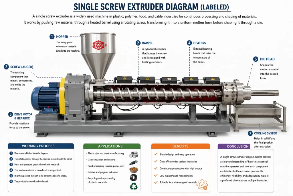
A single screw extruder is one of the most widely used machines in plastic, polymer, food, and cable industries for continuous material processing and shaping. The labeled single screw extruder diagram enables operators and engineers to identify all components and their functions throughout the extrusion process. The machine operates by pushing raw material through a heated barrel while a rotating screw transforms the material into a uniform molten state that the machine shapes through a die. The system operates efficiently in both small industrial environments and large-scale industrial settings because of its straightforward design and its ability to perform multiple functions.
Main Parts in a Labeled Single Screw Extruder Diagram
A typical single-screw extruder consists of several key components, each performing a specific function:
- Hopper: The entry point where raw material (plastic granules or powder) is fed into the machine
- Barrel: A cylindrical chamber that houses the screw and is equipped with heating elements
- Screw (Auger): The rotating component that moves, compresses, and melts the material
- Heaters: External heating bands that raise the temperature of the barrel
- Drive Motor & Gearbox: Provide rotational force to the screw
- Die Head: Shapes the molten material into the desired form
- Cooling System: Helps in solidifying the final product after extrusion
Each part shown in a labeled diagram plays a crucial role in ensuring smooth and efficient processing.
Working Process of Single Screw Extruder
The working of a single screw extruder is continuous and systematic:
- Raw material is fed into the hopper
- The rotating screw conveys the material forward inside the barrel
- Heat and pressure gradually melt the material
- The molten material is mixed and homogenized
- It is then pushed through a die to form a specific shape
- The product is cooled and collected
This process ensures uniform quality and high production efficiency.
Applications of Single Screw Extruder
- Plastic pipe and sheet manufacturing
- Cable insulation and coating
- Food processing (snacks, pasta, etc.)
- Rubber and polymer extrusion
- Recycling and reprocessing of plastic materials
Benefits of a Single Screw Extruder
- Simple design and easy operation
- Cost-effective for various industries
- Continuous production with high output
- Low maintenance requirements
- Suitable for a wide range of materials
Conclusion:
Saini Engineering is a leading Single screw extruder machine manufacturer. We understand the working principle, design calculation, the screw feeds, melts, mixes, and shapes the plastic as it moves through the barrel and exits through the die. Proper design calculations, including screw diameter, L/D ratio, screw speed, throughput, torque, and barrel heating zones, are essential for efficient operation and high-quality output.
For industries looking for trusted extruder manufacturers, we stand out as a reliable provider of Single Screw Extruder machines. Known for their durability, precision, and energy efficiency, Saini Engineering’s extruders deliver consistent performance for a wide range of industrial applications.
We hope our blog will give you a good idea about the parts, working principle, and design calculations of a single screw extruder, and by choosing a reputed extruder manufacturer like Saini Engineering, industries can achieve smooth, cost-effective, and high-quality plastic extrusions every time.